[{1 1}]
2025-06-04
9766
Catalog
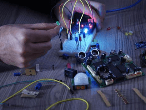
Figure 1: The Use of Breadboards
What is a Breadboard?
A breadboard is a popular tool for prototyping circuits, commonly used by hobbyists, students, and engineers. It’s a solder-free, reusable board designed for building and testing various circuits. A breadboard consists of a grid of holes with metal clips underneath, which securely hold electronic components when inserted. This setup allows for quick construction and easy modification of circuits without the need for soldering. Breadboards facilitate rapid prototype design and testing due to their solder-free and reusable nature. They are widely used in circuit design and educational settings. By leveraging the breadboard’s structure and connection principles, users can quickly build, modify, and test circuits, improving design efficiency and success rates. Adhering to standardized jumper usage and component placement methods further simplifies the layout and enhances troubleshooting efficiency.
Through-Hole Breadboard Components
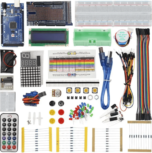
Figure 2: Through-Hole Breadboard Components
Through-hole breadboard components offer great flexibility and convenience for designing and constructing electronic circuits. These components can be easily inserted into breadboard holes to create secure electrical connections without soldering, simplifying the prototyping process.
Resistors
Resistors serve two main functions in electronic circuits, the limiting current and setting specific parameters for components. They act like traffic controllers for current, to ensure manageable flow levels that protect sensitive components and ensure stable circuit operation. Resistors limit current by providing resistance, which prevents circuit overload and protects sensitive components from excessive current. This helps maintain the circuit's stable operation. By choosing the appropriate resistance value, engineers can adjust the behavior and performance of the circuit to achieve desired functions. For instance, in an amplifier circuit, the resistors determine the amplification factor and frequency response.
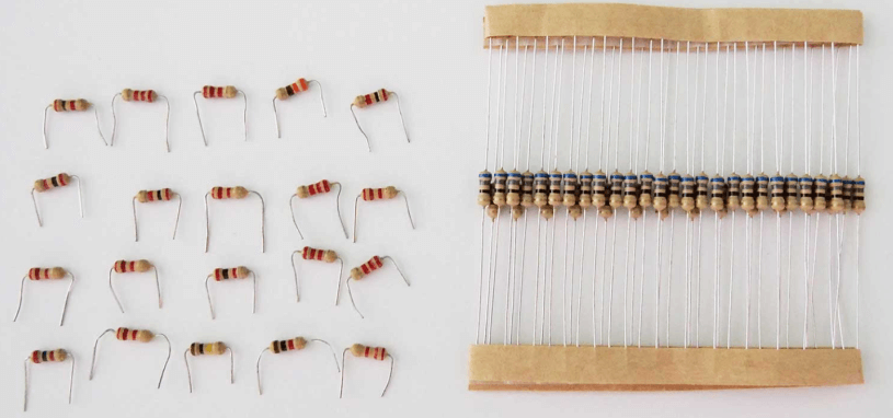
Figure 3: Resistors
Fixed resistors have preset resistance values, determined during manufacturing. Measured in ohms (Ω), their values range from milliohms to megohms. They are used in applications requiring stable and precise resistance, such as filters, voltage dividers, and current limiting circuits.
Variable resistors, or potentiometers, allow users to manually adjust resistance by rotating or sliding a controller. These are useful in applications like volume controls and dimmer switches, providing flexibility to adjust circuit performance as needed.
Select the resistance value based on the circuit's operating voltage and current to ensure the resistor can handle the power. Common power ratings, measured in watts (W), include 1/8 W, 1/4 W, and 1/2 W. Choosing the correct power rating prevents overheating and damage.
The material and manufacturing process affect resistor performance. Carbon film resistors are cost-effective and offer a wide resistance range but lack precision and stability. Metal film resistors provide higher accuracy and stability, suitable for high-precision applications. Additionally, consider the temperature coefficient, which indicates how resistance changes with temperature. For applications with significant temperature variations, low-temperature coefficient resistors ensure stable performance. The layout and connection method of resistors affect circuit performance. In high-frequency circuits, lead inductance and parasitic capacitance can impact the frequency response. Proper layout and wiring can minimize these effects and improve overall circuit performance.
Capacitors
Capacitors are functional in electronic circuits for storing and releasing charge, providing instantaneous power, and smoothing voltage fluctuations. They come in various types, each suited for specific applications. A capacitor stores charge between two conductive plates separated by an insulating material, known as the dielectric. When voltage is applied, charge accumulates on the plates and is released. This enables capacitors to filter power, couple and decouple signals, and store energy in circuits.
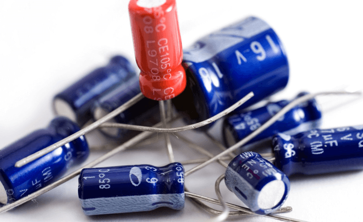
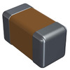
Figure 4: Capacitors
Tantalum capacitors are compact, high-capacitance components with low leakage current and long life. They are ideal for high-density circuit boards in devices like smartphones and laptops, where they provide stable power filtering and energy storage. It’s useful to connect tantalum capacitors correctly, as reversing polarity can cause damage or circuit failure.
Electrolytic capacitors have large capacitance and high voltage tolerance, making them suitable for power supply filtering and voltage stabilization in power adapters, audio amplifiers, and industrial power systems. They smooth power supply voltage and reduce ripple, enhancing power stability and circuit reliability.
Ceramic capacitors are small, cost-effective, and non-polar, with excellent high-frequency characteristics. They are used in high-frequency circuits and signal coupling applications.
Film capacitors excel in high-voltage resistance and stability, making them suitable for AC power supply filtering and pulse circuits.
Choosing the right capacitor involves considering parameters like capacitance value, voltage rating, temperature coefficient, and ESR (equivalent series resistance). For power supply filter circuits, select electrolytic capacitors with large capacitance and low ESR to effectively filter power supply ripple. In high-frequency signal coupling circuits, ceramic capacitors with good high-frequency characteristics are essential to ensure signal integrity.
Switches
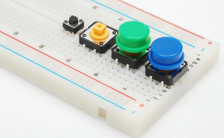
Figure 5: The Switch on The Breadboard
Switches in breadboard experiments control the circuit's on and off states, much like buttons on a remote control. They not only turn circuits on or off but also enable various functions through different types of switches.
Push button switches operate like doorbells. Pressing the button temporarily connects the circuit, allowing current to pass. Releasing the button disconnects the circuit. This makes them suitable for short-term control tasks like reset or start buttons. Toggle switches work like home light switches. They maintain a stable on or off position, changing the circuit state when toggled. Toggle switches come in two main types, the single-pole single-throw (SPST) and Single-Pole Double-Throw (SPDT) single-pole single-throw (SPST) has one input and one output for simple on-off control. And the single-pole double-throw (SPDT) has one input and two outputs, allowing switching between two outputs for more complex control. Slide switches change the circuit state by sliding to different positions. They are used for selecting power modes or adjusting device functions. Their compact design makes them ideal for limited space circuit designs.
Ensure the switch's rated voltage and current match the circuit requirements. Overloading a switch can cause contact burn-out or failure, disrupting circuit operation. Indicates the number of operations a switch can handle before failing, usually in tens of thousands. High mechanical life is required for frequently operated switches. The force needed to operate the switch. Appropriate force improves user experience and control precision.
Potentiometers
Potentiometers, or variable resistors, are important for adjusting voltage and current in electronic circuits. They offer precise control, much like the volume knob on a speaker. By changing their resistance value, potentiometers regulate voltage and current distribution, making them versatile for various applications.
Single-turn potentiometers adjust resistance with a single rotation. They are simple, cost-effective, and durable, making them suitable for tasks like volume control, light dimming, and motor speed adjustment. These potentiometers provide adequate adjustment accuracy for most everyday uses. Multi-turn potentiometers are designed for applications requiring high precision and fine adjustments. They change resistance through multiple rotations, often up to 10 turns or more. This allows for precise resistance adjustments, ideal for scientific instruments, calibration equipment, and precision measurement devices. Although more expensive due to their complex structure, their precision is required for demanding applications. Trimmer potentiometers are used for precise circuit calibration, especially in the manufacturing and testing of printed circuit boards (PCBs). These small potentiometers are mounted directly on PCBs and adjusted by turning a small screw. They allow for subtle adjustments to ensure devices meet design specifications. Adjusting trimmer potentiometers requires precision and professional tools.
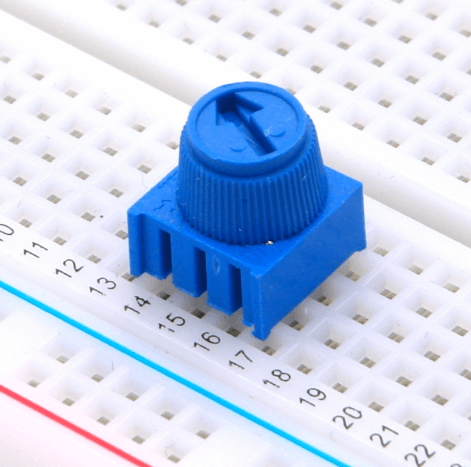
Figure 6: The Potentiometer on the Breadboard
Diodes
A diode is an electronic component that allows current to flow in only one direction, similar to a valve. It is based on the characteristics of a PN junction. When forward biased, the diode conducts current; when reverse biased, it blocks current flow.
LEDs emit light when forward current flows through them. They are widely used in lighting, indicators, and display screens. The light emission is due to energy release when electrons and holes recombine in the PN junction. By altering the semiconductor material, LEDs of different colors are produced to meet various needs. These diodes have a low forward voltage drop and fast switching speed, making them ideal for high-frequency and low-voltage circuits. Zener diodes are used for voltage regulation and protection. They allow current to flow in the reverse direction when a specific voltage is reached, maintaining a constant voltage.
Choosing the right diode types and parameters can help circuit performance and reliability to ensure the diode has sufficient margin for current and voltage to operate safely. Consider the reverse recovery time and forward voltage drop to optimize circuit efficiency.
Get Started with Breadboard Kits
For beginners, navigating the wide range of breadboard components and accessories can be daunting. Breadboard kits provide an easy entry into electronic prototyping, offering a comprehensive set of components and tools that make the learning process intuitive and engaging.
Breadboard kits typically include a solderless breadboard, various electronic components (resistors, capacitors, diodes, transistors, etc.), connecting wires, power modules, and basic tools. These kits help beginners understand the characteristics and applications of electronic components through hands-on experiments. Starting with simple circuits and progressing to more complex ones, users learn the basics of electronic circuit design.
ARD-02 201 Arduino Basic Starter Kit: Designed for users with some electronics knowledge, this kit includes everything needed to build 15 projects, such as temperature sensing and LED control. Users gain an in-depth understanding of Arduino, learning how to use sensors and actuators to create various electronic projects.
ElectroBOOM 101 Kit: Perfect for those new to prototyping, this kit features a 15V-powered solderless breadboard and a multimeter. Users can experiment with different components to understand their roles and performance in circuits, accumulating practical experience and enhancing their electronic design skills.
CSI-01-KIT Basic Electronic Parts Kit: Ideal for both beginners and experienced enthusiasts, this comprehensive kit offers a variety of breadboard components. It allows users to understand different electronic components' characteristics and usage in a structured learning process. Additionally, the kit is cost-effective, providing extensive resources at a lower price.
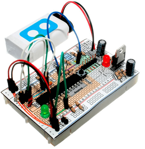
Figure 7: ARD-101 Breadboard Arduino Compatible Kit
Battery Buckles and Battery Clips
Battery buckles and clips simplify the process of connecting batteries to breadboards, offering a flexible and convenient power solution. To connect, attach the positive and negative ends of the battery clip to the corresponding terminals of the battery, then insert the connecting pins into the breadboard’s power rails. This straightforward process enhances the efficiency of circuit construction.
Using portable power sources allows electronic projects to operate without being tethered to fixed power outlets, increasing mobility and portability. This is particularly beneficial for projects that require testing and demonstration in multiple environments. Battery clips enable easy connection of various battery types (such as 9-volt batteries, AA, or AAA packs) to the breadboard, providing a stable DC power supply.
Selecting the appropriate battery type for effective circuit operation. Different batteries offer varying voltages and capacities. For instance, 9-volt batteries are suitable for higher voltage requirements, while AA or AAA packs are better for applications needing lower voltage but longer battery life.
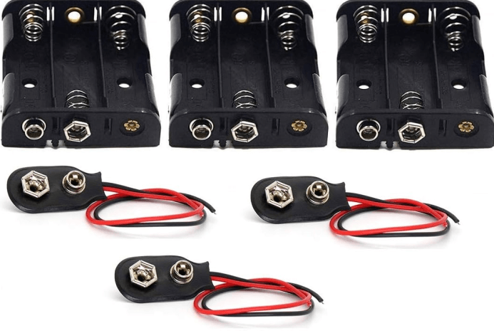
Figure 8: Battery Buckle and Battery Clip
The connection quality between the battery clip and the battery directly impacts power stability and reliability. High-quality clips, made from durable materials and precise manufacturing processes, ensure reliable electrical connections, minimizing contact resistance and power loss. It is required to match the positive and negative poles of the clip with the corresponding battery terminals to avoid short circuits or battery damage.
Adding a filter capacitor between the battery and the breadboard can further stabilize the power supply. The capacitor smooths voltage fluctuations caused by the battery's internal resistance and connection contact resistance that provide more stable power input.
Regularly monitor and manage battery power to maintain circuit performance. As battery power depletes, voltage drops, potentially affecting circuit operation. Regularly check battery voltage and replace or recharge batteries as needed to keep the circuit in optimal working condition. For major projects, consider using a battery box or clip with a power indicator to monitor battery status in real time.
Binding Posts and Banana Plugs
• Binding Posts
Binding posts are effective connectors to stabilized stable electrical connections on breadboards. Designed like small screws with nuts, they securely attach to breadboards. Insert the binding posts into the holes, and tighten the nuts to ensure a firm connection. This setup allows reliable attachment of wires, resistors, capacitors, and other components to the circuit.
Binding posts are made from highly conductive materials like copper or nickel-plated brass that offers excellent current conduction. Tightening the nut reduces contact resistance and prevents electrical failures from loose connections. These posts are designed to handle both electrical and mechanical demands, provides strong mechanical stability while withstanding large electrical loads.

Figure 9: Binding Posts and Banana Plugs
• Banana Plugs
Banana plugs are designed to work with binding posts. Their spring-like structure ensures a secure connection when inserted into the binding post, generating enough contact pressure for a firm electrical link. Using banana plugs makes it easy to connect and disconnect components, reducing wear on terminals and plugs, thereby extending their lifespan.
The combination of binding posts and banana plugs is particularly useful in circuits that require frequent adjustments and testing. For instance, in audio equipment or power module testing, these connectors improve efficiency by allowing quick replacement of test components. The stable connection provided by binding posts is also ideal for high-current applications like high-power power supplies or motor drive circuits. It ensures the system safety and performance.
Binding posts are versatile and can be used with various plugs and connectors. Adding adapters expands their application range, allowing connection of different wires and devices. This flexibility simplifies circuit design and testing. Using binding posts and banana plugs makes maintenance and troubleshooting easier. Replacing or debugging components only requires plugging and unplugging connectors, avoiding complex soldering and disassembly.
Breadboard Structure
The breadboard is designed using thermosetting phenolic resin as the primary material. This material withstands high temperatures, has excellent mechanical strength, and provides superior electrical insulation to ensure breadboard’s stability and durability in various conditions. Embedded within the board are metal strips, machined and electroplated to offer excellent electrical conductivity and corrosion resistance. These strips form electrical connections with the holes on the board, typically connecting every five holes together. This setup allows users to easily insert and secure electronic components for efficient electrical connections.
The center of the breadboard features a groove designed for integrated circuits (ICs) and chips. This groove enables dual in-line (DIP) packaged ICs to straddle both sides, preventing shorts between adjacent pins and provide independent connection points. This design facilitates easier circuit debugging and modification.
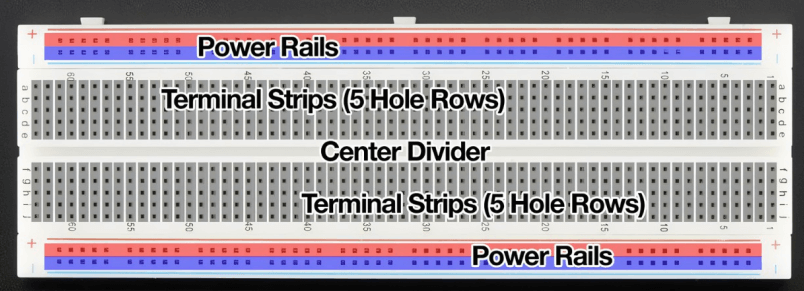
Figure 10: The Structure of the Breadboard
The power rails are located on both sides of the board, usually arranged in two vertical rows of jacks, each containing five holes. These rails are connected by metal strips to supply positive power and ground. For easy identification, power rails are often color-coded, with red indicating the positive supply and blue or black indicating ground. This setup simplifies power distribution across the circuit to ensure components can receive the necessary power.
The breadboard structure not only prioritizes electrical connections but also mechanical stability and user convenience. The layout and hole spacing are designed to allow stable insertion of components, maintaining good electrical connections. The central groove and side power rails enhance circuit design flexibility and operability.
When inserting components, ensure the pins are accurately aligned with the holes to prevent bending or damaging them. Keep jumpers neat and standardized, avoiding overly long or crossed wires that could affect circuit appearance and performance. Regularly check and clean the holes and metal strips to prevent dust or oxides from compromising the electrical connection. This maintenance ensures the breadboard remains reliable and effective for prototyping and testing circuits.
Common Breadboard Specifications
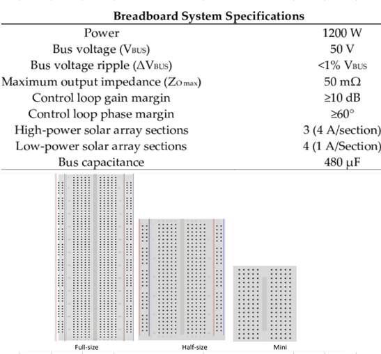
Figure 11: The Specifications of the Breadboard
Solderless breadboards are functional for electronic engineers when designing and assembling demonstration circuits. They provide temporary connections between electronic components, for developing and testing circuits. This allows quick changes without complex modifications. Due to the temporary nature of the connections, breadboards are best suited for low-voltage, low-power circuits and are not recommended for high-frequency signals.
Breadboards feature a grid of contacts spaced 0.1 inches (2.54 mm) apart. This standard spacing accommodates the pins of most transistors and integrated circuits. The number of contact points varies by breadboard size and manufacturer. Small breadboards may have around 70 contacts, while larger ones can have up to 900. Contacts are arranged in 10 columns with a central divider, providing 56 connection points for a 14-pin integrated circuit (4 points per pin).
Breadboards are generally rated for 5 volts at 1 amp or 15 volts at 1/3 amp, equivalent to 5 watts of power consumption. These ratings can differ based on the manufacturer and breadboard type, so checking the datasheet before purchase is a must. Most breadboards have a current limit of 1 amp or less due to the nature of the contact connections.
Breadboards are typically unsuitable for frequencies above 10 MHz. Each connection point introduces approximately 2 to 20 picofarads (pF) of stray capacitance, which can affect high-frequency circuits. The capacitance changes each time a component is inserted or removed, impacting circuit performance.
Capacitance, the resistance to changing electrical current, occurs when two conductors are separated by an insulator. On a breadboard, imperfect connections between leads and contacts create 2 to 20 pF of capacitance at each point. This effect is problematic in high-frequency circuits, as it impacts signal integrity and overall performance.
The spring-contact design of breadboards facilitates quick and easy circuit building but introduces resistance at each connection point. Contact resistance is approximately 0.1 ohms or higher, potentially causing voltage drops and power loss, leading to unexpected circuit behavior.
Breadboard Power Supply
A breadboard power supply functions as a reliable source of energy make sure the circuits run smoothly during testing and experimentation. It provides stable voltage and current necessary for the circuit's operation.
Some advanced breadboards come with built-in power modules, like the 15V solderless breadboard kit. It directly supplies the required voltage and current. Standard breadboards usually require an external power source such as a battery or a DC power adapter, connected via jumpers. The choice of battery—AA, 9V, or lithium—depends on the circuit's voltage requirements and power consumption.
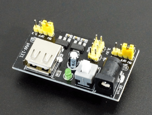
Figure 12: Breadboard Power Supply
To connect the power supply, use a red jumper for the positive terminal and a blue or black jumper for the negative terminal or ground. Attach the positive and negative terminals of the battery to the respective power buses on the breadboard, ensuring even power distribution. When using a power adapter, verify that its voltage and current output match the circuit's requirements and that the polarity is correct.
Using a power module with anti-reverse protection can prevent damage due to incorrect polarity. An adjustable voltage output module is recommended for flexibility, allowing voltage adjustments based on circuit needs. A voltage-stabilized power module is also beneficial in providing consistent output voltage even with input fluctuations.
Monitor the power supply’s voltage and current with a multimeter during tests and experiments to ensure they remain within the design range. If abnormalities occur, check the power connections and the circuit for short circuits or other issues. The multiple power supplies can provide independent power to different sub-circuits, reducing interference and enhancing stability.
Jumper Wires and Breadboard Wires
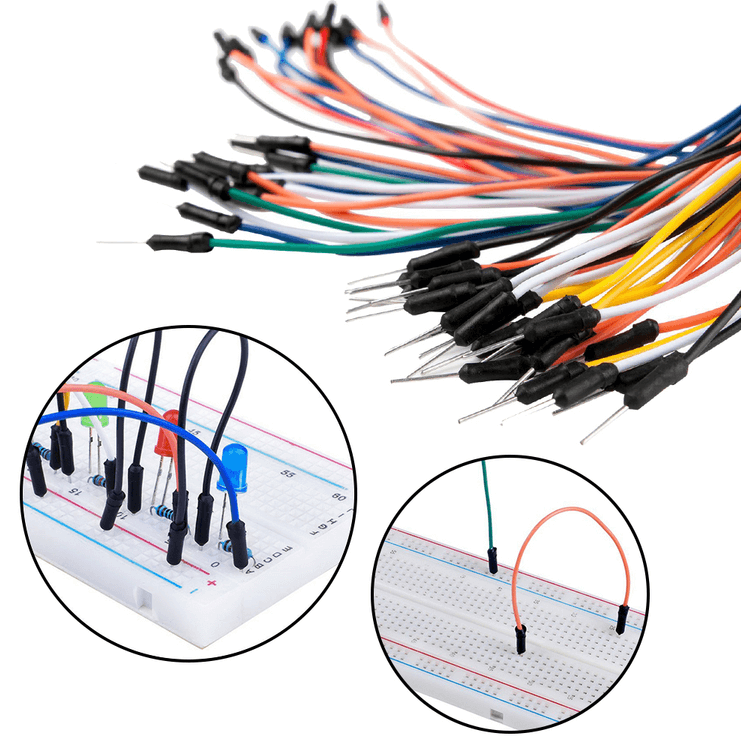
Figure 13: Jumper Wires and Breadboard Wires
Jumper wires are effective to connect various electronic components on a breadboard. It helps ensuring circuit integrity and reliable signal transmission. The common types of breadboard jumpers are male-to-male, male-to-female, and female-to-female.
Male-to-male jumpers have pins on both ends ideal for connecting components within the same breadboard. These jumpers are practical for prototyping that allow easy connections between resistors, capacitors, diodes, and other components. Female-to-female jumpers feature sockets on each end, suitable for linking different parts of a breadboard or multiple breadboards. Useful in large projects where sub-circuits need to be connected that offer a flexible connections and circuit stability and scalability. Male-to-female jumpers are useful connection from breadboard to external devices or connectors, such as sensors, displays, or microcontroller modules. They simplify circuit design and debugging by providing direct connections.
Different jumper lengths are suitable for different scenarios. Long jumpers can clutter the circuit and increase electromagnetic interference, while short jumpers may restrict circuit layout flexibility. Using jumpers of varying colors helps differentiate signal types and power lines, such as red for positive power and black or blue for ground. This color-coding aids in debugging and troubleshooting.
More Breadboard Accessories
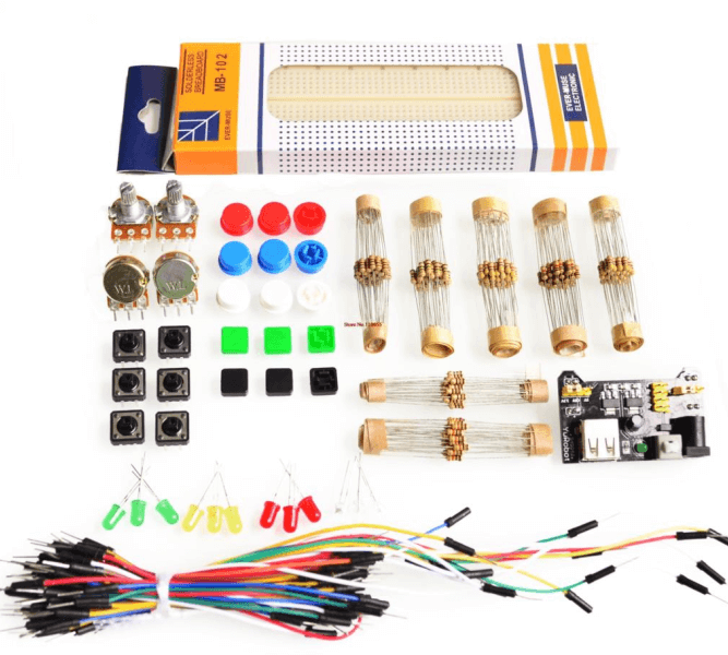
Figure 14: Breadboard Kit
IC Adapters
IC adapters simplify testing integrated circuits on a breadboard. They secure and easily remove ICs for proper pin connections and reduce the risk of errors from manual insertion. This makes testing faster and more efficient.
Prototype Shields
Prototype shields are invaluable for complex projects involving microcontrollers like Arduino. They provide additional space and functional modules, such as expanded I/O ports, communication interfaces, and sensor modules. It simplifies building and debugging circuits, reduce wiring complexity and improve efficiency.
Breadboard Mounting Plates and Adhesive Feet
Mounting plates and adhesive feet stabilize prototypes during testing. These accessories keep the breadboard secure on the workbench to prevent accidental disconnections and ensure accurate readings. This stability is required for long-term testing and debugging that reduce errors and increase work efficiency.
Storage Boxes
Storage boxes designed for breadboard tools help organize and manage projects. With multiple compartments, they store various electronic components and tools neatly to access what you need easily. This organization saves time and enhances workflow efficiency.
Inductors and Motors
Inductor’s store and release electrical energy, smoothing current fluctuations and reduce noise in circuits. Motors add mechanical movement, enable automation and mechanical control. Combining inductors and motors allows for the creation of dynamic, feature-rich electronic projects.
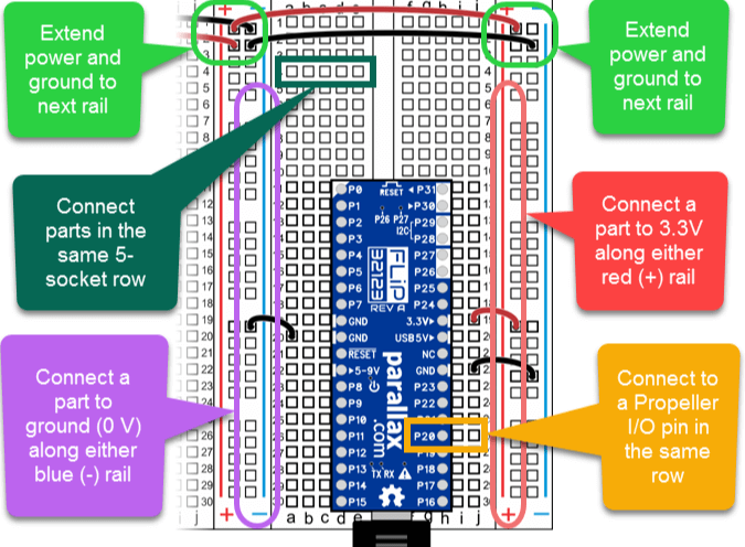
Figure 15: How to Use a Breadboard
Conclusion
Breadboards represent a foundational tool in electronics, merging simplicity and functionality to support a wide range of prototyping activities. Their design, characterized by a grid of holes and embedded metal strips, ensures both mechanical stability and electrical reliability, enabling users to create and test circuits efficiently. By exploring the detailed structure, common specifications, and accessory components such as power supplies, jumper wires, and binding posts, this article highlights the versatility and practicality of breadboards in circuit design. The understanding of component placement, contact resistance, and capacitance effects further underscores the importance of meticulous design and maintenance practices for optimal performance. Whether for educational purposes or advanced engineering projects, breadboards offer a dynamic platform for innovation, allowing users to experiment, learn, and refine their designs with ease.
Frequently Asked Questions [FAQ]
Q1. Are Breadboards Safe?
Yes, breadboards are generally safe for electronics experiments and prototyping. They allow you to build circuits without soldering, reducing the risk of short circuits and damage to components if used correctly. But they are not suitable for high voltage or high current applications.
Q2. How Long Do Breadboards Last?
The lifespan of a breadboard largely depends on how it is used. With careful handling, a breadboard can last for several years. Over time, the springiness of the contact points may degrade, leading to less reliable connections.
Q3. What Are the Limitations of Using Breadboards?
Breadboards have several limitations. They are not suitable for high frequencies. Connections on breadboards can act as antennas, leading to unwanted capacitance and inductance. They have limited current. They cannot handle very high currents without the risk of melting or damaging the board. Also, using breadboards has temporary connections. They provide less stable and less reliable connections compared to soldered boards, which can be problematic in long-term projects or in environments with vibrations.
Q4. Are Breadboards Reusable?
Yes, breadboards are designed to be reusable. You can repeatedly insert and remove components to test and modify circuits without any permanent changes to the board. This makes them ideal for prototyping and educational purposes. Their reusability can diminish if the holes become worn out from frequent use.
suʻega. O oloa e sili ona taugofie ma le auaunaga sili ona lelei o la matou tautinoga tumau.
![[{1 1}]](/upfile/blog/small_2024071818234786371.png) [{1 1}]
[{1 1}]
2024-07-18
![[{1 1}]](/upfile/blog/small_2024071811233263961.png) [{1 1}]
[{1 1}]
2024-07-18
E masani ona fesiligia fesili [FAQ]
1. Can I use a breadboard more than once?
Yes. You can use it many times. Just don't bend the pins too much, or the holes may stop working well.
2. How much power can a breadboard handle?
Most breadboards can handle up to 12 volts and less than 1 amp. Too much power can break it.
3. Can I use AC power on a breadboard?
No. Breadboards are made for DC power only. AC power is not safe to use.
4. Why don't some big parts work well on breadboards?
Big parts like motors or strong transistors need more power than the breadboard can handle. They may also not fit well.
5. How do I make my breadboard bigger?
You can connect two or more breadboards side by side. Some can snap together or be taped down.
VAI VAEGA Numera
 GRM2195C2A152JA01D
 250X15W104MV4E
 CL21F105ZOCNNND
 GCM1885G1H330JA16D
- GRM21BR61C334KA01L
 06033A151GAT2A
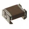 KC355LD72E474KH01K
 GRM32MR71C225KC01L
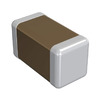 GRM1557U1HR90CZ01D
 X9268US24Z
- CY7C64215-28PVXCT
- HIN232ACB
- A6B595KLW
- CM75E3U-24H
- MAX1110CAP
- AL8821SP-13
- VE-J10-MY
- MAXM17504ALJ+
- MPXV2010GP
- VI-J6Y-IX
- 7MBP150RTB-060
- CM400DU-24NFJ
- QM20KD-HB
- LT1965IDD#TRPBF
- STM8S103K3T3CTR
- LTC3851EMSE-1#TRPBF
- ADA4610-2ARMZ
- XC3S400-4PQG208I
- TUSB422IYFPT
- TL1963A-18DCYR
- T495A105K020ATE5K0
- MC34060ADR2G
- TL16C550CIFNR
- T491D475M050ZTZQ01
- LM3S1958-IQC50-A2
- XC5VLX155T-2FFG1136I
- EE80C188XL12
- MAX5122BEEE
- RF1113ATR13
- SC667298C
- X9421IWSZG
- CV34L-T48DV1
- UPD82874NF
- AFEM-8074-AP1
- TMS470AVF3482EPZI
- UPD61283F1-407-LU2-A
- SN74LVC1G08DBV
- CRCW080575KOFKEA
- BZV55B3V9